Reverse Engineering
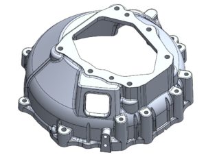
Our client, Quality Products, had an old automotive bellhousing made from cast aluminum. They wanted to replicate the exact same part as a single CNC machined piece out of aluminum billet. Their dilemma was that they had a physical sample of the part they wanted reproduced but did not have any documentation or CAD of the part to use for machining. To remedy this, they could either use precision instruments to painstakingly measure every detail and datum to recreate the part, or use a more sophisticated approach.
Since time and cost is always a factor, they contacted NLS with interest in our 3D  scanning and reverse engineering services. They delivered the sample of the bell housing to us, which had an overall size of roughly 17” W x 20” L x 10” H. There was no denying that the part was large and would be a challenge to 3D scan and map with all of its intricate geometries and interior features.
To scan a part of this size, we did what any good engineer does when faced with a difficult challenge; break it down into parts and solve incrementally. The bell housing was coated and marked with dots in a grid pattern. The exterior surfaces of the housing were scanned section-by-section, with some sections requiring multiple passes at varying scan angles to capture all the details. Next, the top and bottom sides of the part were scanned before finally flipping the part and scanning the inside surfaces. In total, nearly 30 individual scans were performed on this part.
Once all the scan data was rendered, it had to be mapped together to reconstruct the 3D representation. The grid pattern dots aided in this task as the dots were used as reference points for relating one scan image to the next. With all of the individual scan images mapped and spliced together, a 3D surface model could be imported into SolidWorks to begin building up an actual CAD model.
Using the 3D surface scan as a reference, one of our talented engineers created a fully editable 3D model of the part. The new model captured the contoured surfaces, openings, and hole locations brilliantly. Upon the completion of the model, a supporting engineering drawing was created for the part as well. At the end of the project, all of the scan data, CAD model, and engineering drawing was delivered to the customer, giving them the tools they needed to recreate this part as needed.
